


Posted with thanks from Lee West


With thanks from Andy Bebbington


With thanks from Jon Woodcock


Posted with thanks from Lee West
With thanks from Andy Bebbington
With thanks from Jon Woodcock
The ini file sets the defaults for the Rc2040 and substitutes for switches and buttons on boards that have none.
It allows you to select the ROM, RAM settings, and CPM settings for the emulation.
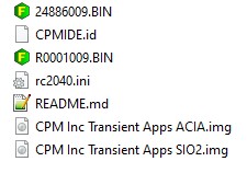
Requires CPM Inc Transient Apps SIO2.img,CPMIDE.id, 24886009.BIN and rc2040.ini for SIO2 as below
ROM has basic at address 0x0000 (000) ROMsize 0x2000
ROM has basic at address 0x2000 (001) ROMsize 0x2000
CP/M / Basic via monitor at address 0x4000 (010) ROMsize 0x4000
Small Computer Monitor at 0xe000 (111) ROMsize 0x2000
More detail at [https://github.com/RC2014Z80/RC2014/tree/master/ROMs/Factory]
Config with no switches and other emulation settings for SIO2
[IDE]Config with no switches and other emulation settings for ACIA
Requires CPM Inc Transient Apps ACIA.img,CPMIDE.id, R0001009.BIN and rc2040.ini as below
Rom has basic at address 0x0000 (000)
CP/M via monitor at address 0x8000 (100)
Small Computer Monitor at 0xe000 (111)
More detail at [https://github.com/RC2014Z80/RC2014/tree/master/ROMs/Factory]
Config with no switches and other emulation settings
[IDE] idefile = “CPM Inc Transient Apps ACIA.img”;// Size of ROM
romsize=0x4000;
#ROM file as ROM source romfile = “R0001009.BIN”; // source for Rom Loading – see a13 a14 a15
[CONSOLE] // Console port 0=UART or 1=USBYou can edit the contents of the SD card .img file using CPM Manger and directly add or remove files in the CPM img.
CPM Manager is available here.
If you are using Linux (or windows), you can use the CPM tools to add or remove files. CPM tools are available here If you are using CPM tools, you will need a diskdef files. Disk defs for the RC2040 format(s) are available here DiskDefs
8 bits of a simple IO post are brought out to the RP2040 GPIO as an input/output port. The port is configured on the fly, So if you execute an IN instruction, the port becomes an input port, (with pull ups). If you execute an OUT instruction the port becomes an output port. (The Original RC2014 port is arranged as 8 outputs and 8 inputs, but there were only 8 bits available. )
Details are in the Circuit diagram . Switches and buttons are not required. But give you direct access to the ROM addresses (top 3 address lines) and the buttons allow for a z80 reset, Dump and other functions.

A complete kit of parts for the RC2040 is available here from Extreme Kits
The easiest way to do this is to go to the latest release of the RC2040 Git hub and download the RC2040.uf2 Plug in your PICO and drop the uf2 file into the Pico
Take an empty SD card (this process will destroy ALL the data on it)
Format the card with a FAT32 filesystem either using windows format or a SD card writing program.
From RC2040 Git hub download the source_files zip (or tar) and extract the SD Card Contents directory.
Copy the contents of the ‘SD Card Contents’ directory onto the newly formatted SD card. You will need to unzip “CPM Inc Transient Apps ACIA SIO2.ZIP”
Wire in the SD card to your Pico or RC2040 board


For communicating with the RC2040, there are two options. By default the RC2040 uses the USB interface. When the RC2040 starts this should appear as a serial port on you connected computer.
I use Terra term, but MiniTerm or putty should work ok too.
#TODO add MiniTerm and putty details
Open Tera Term and select the newly added serial port

The COM port will vary, but it is usually the last one in the list.
Speed 15200, 8Bits, No parity, 1 stop bit, No flow control.
If you are doing copy and paste via serial, you will also need to set the transmit delay of 1mS per character and 3ms per line to prevent serial overruns.
Click New open and hit enter…
Hopefully you should see
_______________________________________________________________________________
A complete kit of parts for the RC2040 is available here from Extreme Kits
Continuing from Emulating a Z80 RC2014 with CPM and IDE drives via an SD card here..
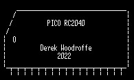
The RC2040 is an emulated RC2014 (a build your self Z80 computer). But this one is entirely contained within a RP2040 (Raspberry Pi PI Pico) processor.
On the RC2040 you can Run any RC2014 Stock ROM image. including Basic and various Z80 monitors and CPM monitor. (except RomWBW there isn’t enough RAM)
RC2014 Rom Image details are here
Details on running the various RC2014 ROM based programs are here
Emulated ROM and RAM is a bit weird, because internally it’s all actually RAM, but the RC2040 allows a user definable area of RAM that is read only, or no ROM at all.

It also allows loading of RC2014 ROM images (rather than programming ROMS or EPROMs) directly from the attached SD card.
With CPM the RAM is more interesting, as CPM starts running from a ROM, but when it loads, the ROM is switched out so it can use the full 64K RAM. This is achieved in the RC2040 by simulating the RC2014 RAM/ROM card that allows an IO port to “swapout” or disable the ROM

Running the CPM monitor from the ROM, allows you to run any CPM-80 compatible program. There are hundreds out there and they include BASIC, Infocom Adventures (Zork, Hitchhikers) Wordstar, Startrek this list is endless.
CPM of course requires disk drives. These are emulated in file(s) on the SD card. The format is similar to the format used in the RC2014 CF card module (and with some simple changes, It will also work with the same CF images).
Instead of the CF format, the RC2040 uses a .img format, this makes it directly compatible with the CPM images from the RC2014 web site. But for CPM to work we also need a drive geometry structure which matches the .img, this is provided with an additional .id file.
The img format gives 128M of drive space, Split into drives from A-P

The img file system also makes it directly compatible with CPM Disk Manager which allows you to directly write into the CPM img file from your computer, which saves a lot of time when transferring software to your RC2040
The RC2014 uses its serial port to talk to the world. The RC2040 has the ability of using either its own USB embedded serial port, or a physical serial port similar to the RC2014’s this is selectable (see ini file settings )
The RC2040 also allows you to run with two different serial port configurations ACIA and SIO. Unfortunately you need a different ROM and CPM bios to work with each serial port type. Hence the selection in the Github SD card section. (again this is selectable via ini file settings.)

The CPM IDE images come with a few CPM programs to get you started. Anything ending in .COM will run directly from CPM. anything with a .BAS extension needs you to run basic first (c:MBASIC) then load the program (load “programname.BAS”) and then run.
More details on running CPM are here
A complete kit of parts for the RC2040 is available here from Extreme Kits
Ive always loved Z80’s Even before programming in high level languages I was had compiling Z80 code on a Nascom1
Recently I’ve discovered the world of emulated Z80’s via the emulator written for linux by Alan Cox (Etched Pixels) (https://github.com/EtchedPixels/RC2014) This allows various configurations of Z80 RC2014 (https://z80kits.com) machines to be emulated (along with 8080 8086 and may other 8 and 16 bit processors)
My C code was rather rusty and I wanted a project to re teach me the basics.
Starting with the Etched pixels code I quickly got it running on a Raspberry PI Zero and added a few simple peripherals.

Which is all fine, but well it was, all a bit easy.
So, I was looking for a project to play with the RP2040, ideal, apart from The RP2040 doesn’t give a linux OS, It doesn’t have any storage (other than its own flash) and it only has 240K of memory.
To emulate a CPM system you need a minimum of 64K (plus a switchable ROM) some form of storage, ideally removable. Some way of loading the ROM (although this can be compiled in as an image) and a serial terminal.
Well the serial terminal is easy, there are 4 plus USB to play with, although all of the emulation uses STDIO uniquely, which is only partially supported on a PI Pico in C
As I was only interested in the Z80 bits of the emulation and only with the peripherals commonly supported on an RC2014. I started on the Raspberry pi, removing all of the other non z80 library’s and the other peripherals I wouldn’t need.
This was easy, rip a bit out, patch the code so it didn’t require it, edit the make file, recompile, test. Repeat until you have a basic Z80 emulated machine.

The ROM, I temporally coded into C via the linux xxd command, from one of the factory ROM’s available on the RC2014 git hub. https://github.com/RC2014Z80/RC2014/tree/master/ROMs/Factory
The next problem is that the emulator as configured uses 512K of ram (RC2014 – 512k ROM 512k RAM Module) to emulate a paged ram card. As the RC2040 only has 240K of memory I needed to remove the Ram/Ram paged memory code and replace it with a 64K ram/Rom paged emulation (RC2014 64k RAM Module and RC2014 Pageable ROM Module), that will only take at max 128K. It also must allow for the ROM to be paged out to allow the bootloader to be installed at 0x0000.
Using the compiled ROM I could easily fill an array of uint_8 with a ROM image, and switch using port 0x38 as a RC2014
CPM was emulated using the EtchedPixels code for a removable CF card. The Binary is readily available already configured to boot on an RC2014 again from the RC2014 git hub https://github.com/RC2014Z80/RC2014/tree/master/CPM
From the CPM source image (.img) file, you need to make an IDE file system onto a .cf file. using CPMtools. Details are towards the bottom of this page under “CP/M Application Disks” https://github.com/RC2014Z80/RC2014/tree/master/ROMs/CPM-IDE
Luckily this CF file can again easily be tested by loading up the image using the RPI z80 linux emulator.
Of course the Pico doesn’t have any storage like a CF card and the 3.3v bus makes interfacing to a 5v CF difficult, but there is the possibility of using a SD card via SPI.
Luckily there is a library for SD cards which works with the PICO no-OS-FatFS-SD-SPI-RPi-Pico https://github.com/carlk3/no-OS-FatFS-SD-SPI-RPi-Pico
Working through the example was straight forward and gives a great way to test your SD card connections and if required, format a fat32 SD card.
The connections to the SD card are simple, 4 wires and power.

At this point there is no way we can test the code on a RPI, so we need to dive into the PICO.
Compiling the code to the PICO without IDE support was surprisingly straightforward. All that was required was to replace the TX/RX STDIO calls with a call to the PICO UART. Unfortunately there was no easy non-blocking call to the receive queue using the USB serial. So initially the input/output was all via the hardware serial port.
I tackled the SD card next, making a simple bit of code to read a 64K rom image from the CD card directly into the ROM array, so I could remove the horrible compiled C ROM. The ROM images came directly from the RC2014 Factory ROM images on Git hub.
To make the ROM selection easier I added three switches to emulate the RC2014 A13, A14, & A15 ROM select jumpers, This meant I could easily switch between ROM starting addresses when loading from a rom image.
As I was adding switches, I decided to add a few buttons. which give me a Z80 reset and a dump RAM initially as a hex dump to the terminal, and latterly as a .bin file into the CD card for debugging.
To allow for a switch-less operation for the switches / buttons to work you need to ground GPIO 22, otherwise the RC2040 will run with switch-less defaults( currently CPM ROM and USB serial)
I changed the IDE library to use the FatFS-SD-SPI-RPi-Pico file system and pointed it to load the .cf image from the card.
After A LOT of playing around with the differences in read/write and seek, plus RAM/ROM switching and serial problems. It finally loaded 🙂
I also found that if I disabled the RAM/ROM switching on a emulated z80 reset (from the button), I could warm boot into CPM, bonus…
Eventually I sorted the problems with the blocking USB serial by writing an interrupt driven routine that fills its own circular buffer, so now (from a switch) you can select which serial port you prefer.
If you don’t need the switches/ buttons, you can run it without, using a Pimoroni Tiny 2040 using the USB serial, making the smallest z80 CPM machine, ever (unless you know different?)

vbnvbn
All of the files to emulate a Z80 with IDE on SD are available via git hub https://github.com/ExtremeElectronics/RC2040
Unfortunately I haven’t quite solved the Serial issues yet. The serial interface(s) will only take characters as a really slow rate. If you are going to cut/paste code into the RC2040 you will need to add in a 40mS (or longer delay) into your terminal program.
Serial issues are much improved. If added a block to the RX char circular buffer code that will only allow char RX, if the ACIA isn’t currently in an interrupt and added a fake interrupt to drive the USB RX circular buffer in the same way as the UART RX
Added SIO support and some bodges to delay the emulated interrupts to allow serial as fast as the Z80 emulation can cope with.
Using Terra term I can now drop files onto the RC2040 with only a 1ms TX delay.
Continued here

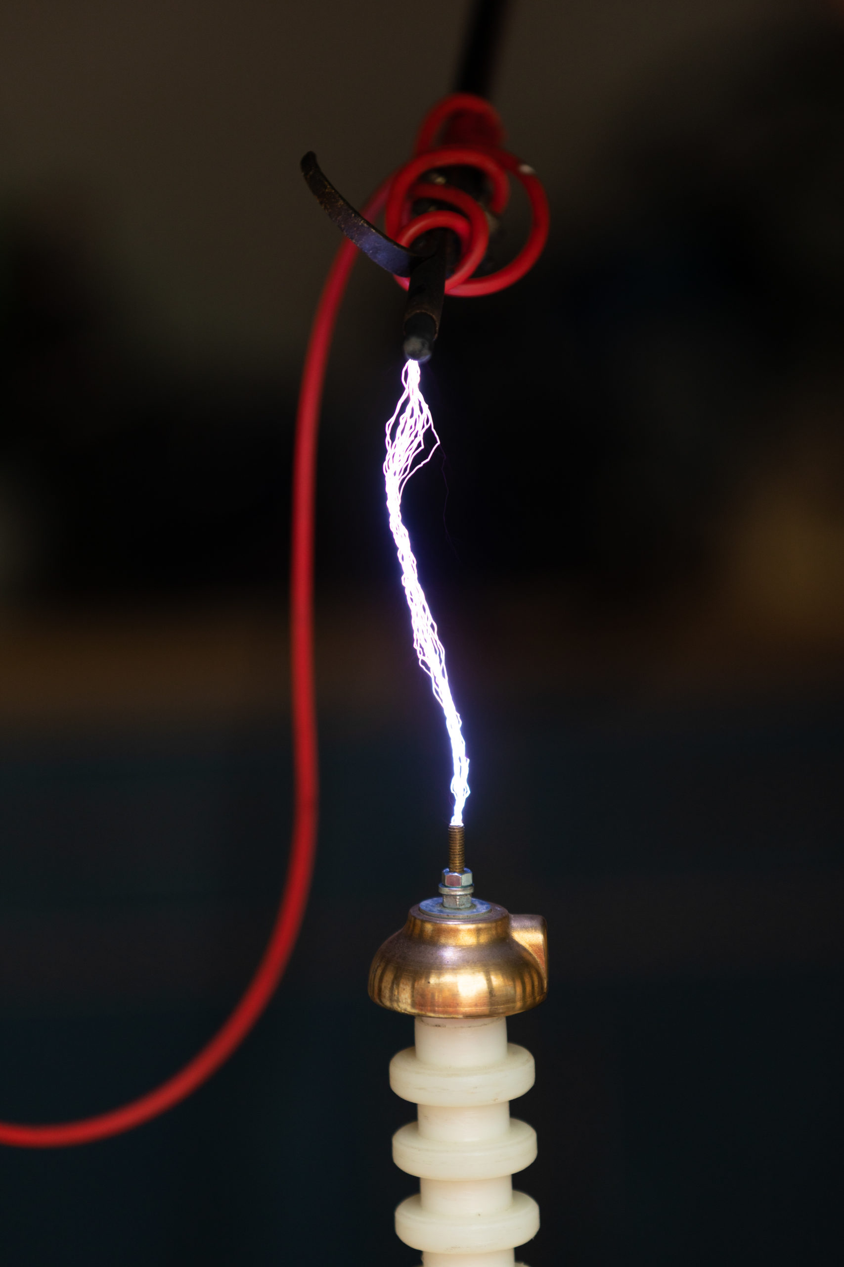
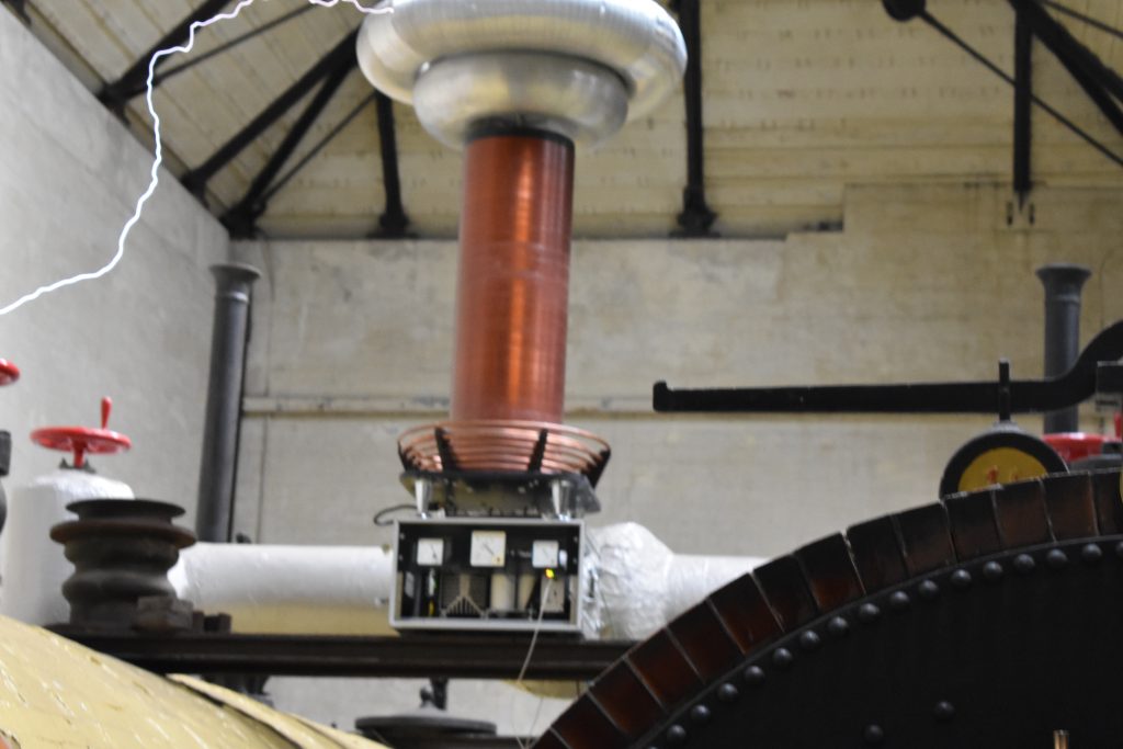
Finally back to meeting Tesla coilers. Although in October….
A collection of photos..,.


Sorry it took so long to update the pages… Y’know stuff happened….
Ok, so not an actual ION drive, but a thruster based on the “lifter effect”
The rough idea is you have a grid of spikes, or in this case some thin wire, acting as a corona wire. In front of this is an array of flat, wide earthed electrodes. The electrons are accelerated from the points or wires towards the earthed electrodes. As this is in atmosphere, the air is dragged along with the ion flow, causing a noticeable “wind”

Frame for the thruster
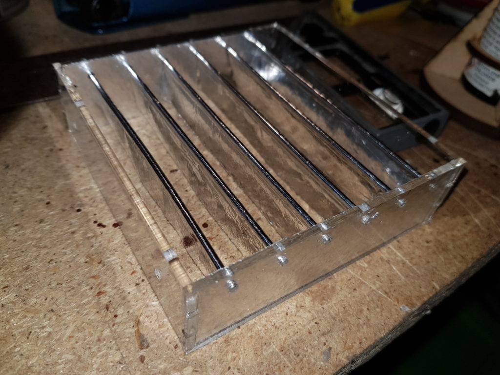
Earthed electrodes in front of the corona wires. This assembly is arranged so the gap between the wires and these electrodes can be adjusted by sliding them in and out.

Built Thruster on stand. 40Kv to the corona Wires

Corona Wires

Thrust indicator fan.

Thruster and fan setup.
Video of thruster running. Plus Corona on the wires.
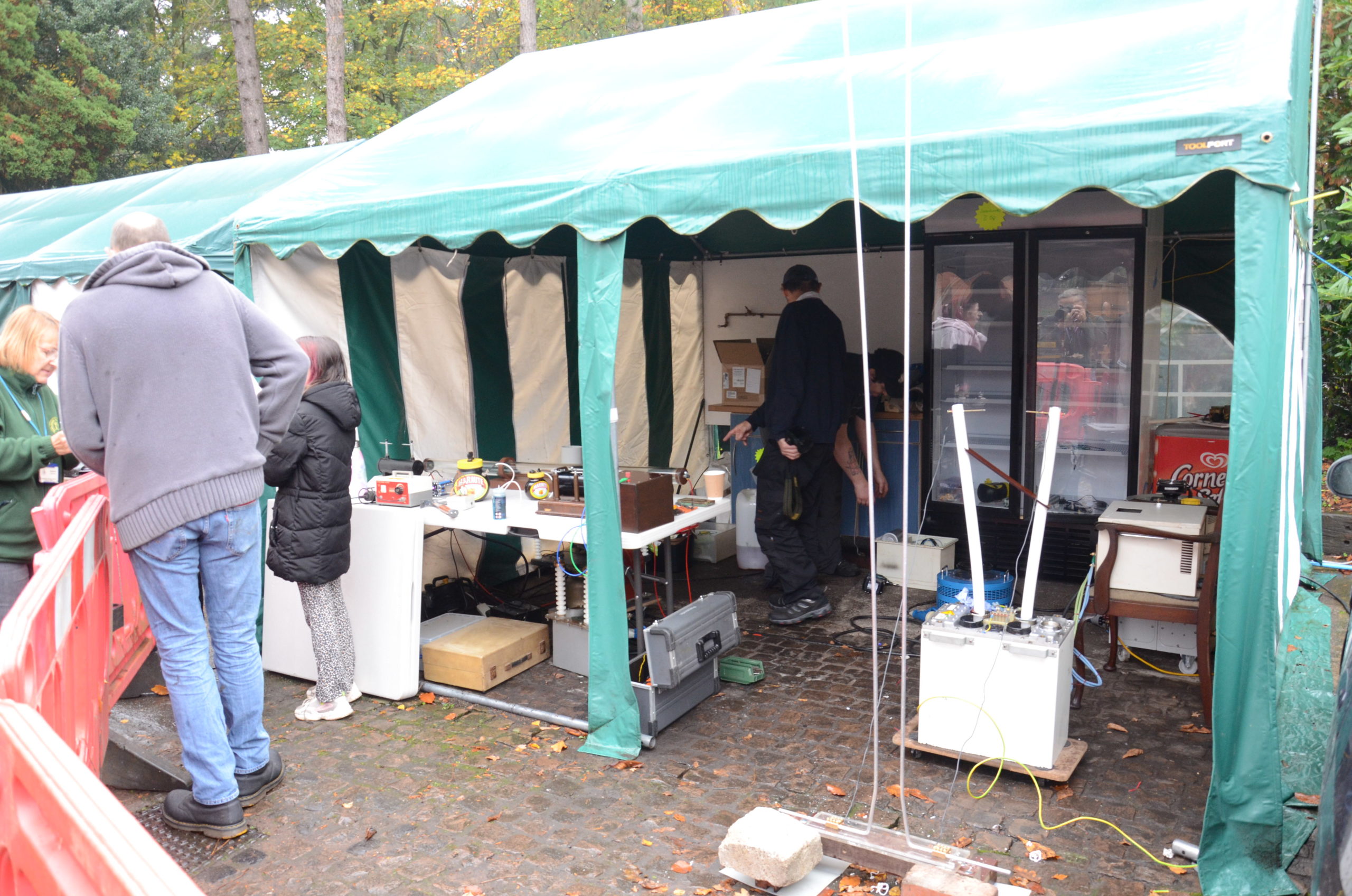
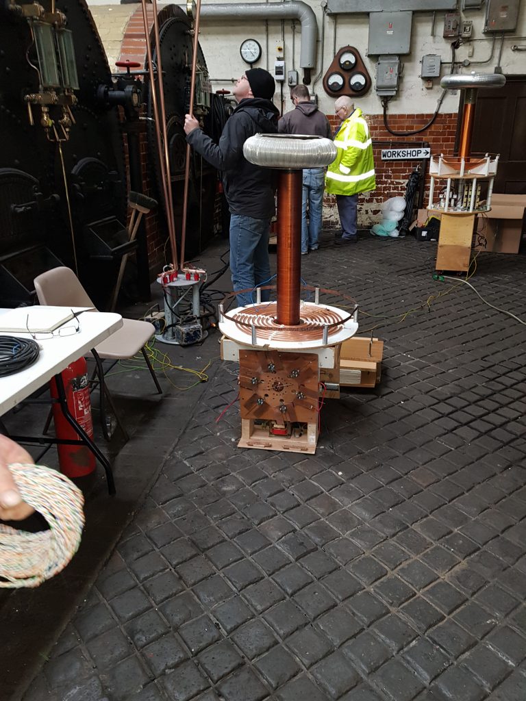
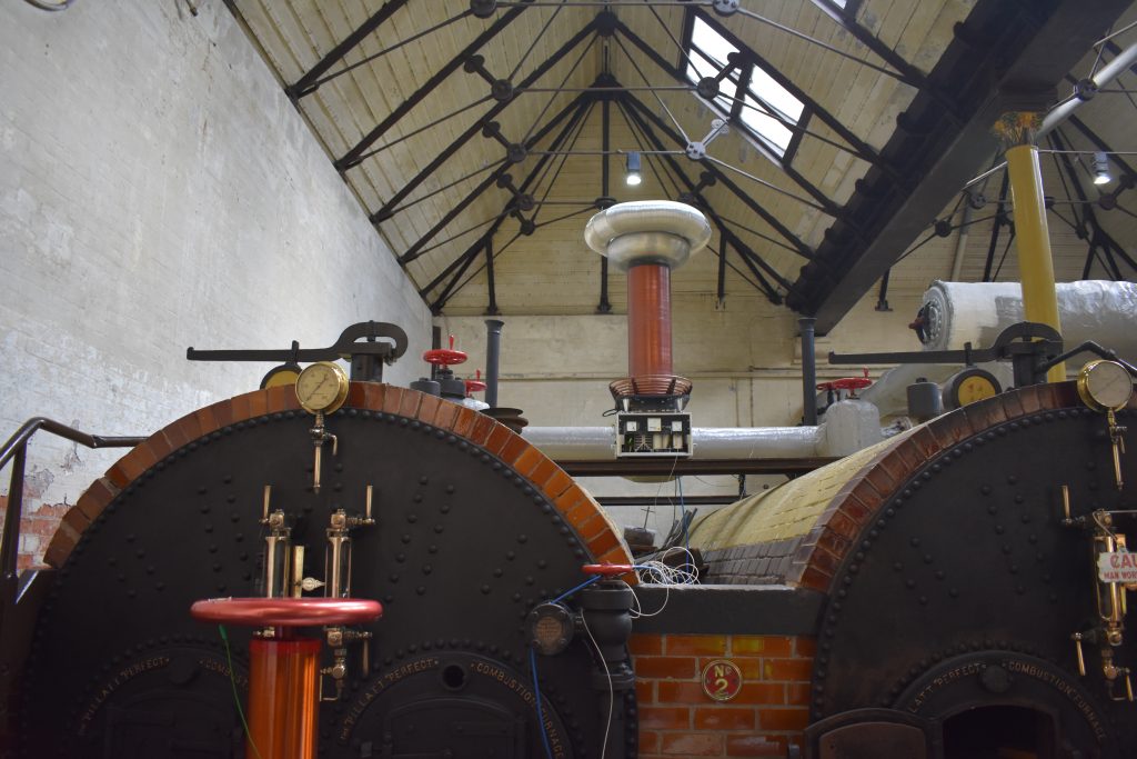
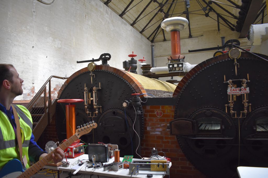
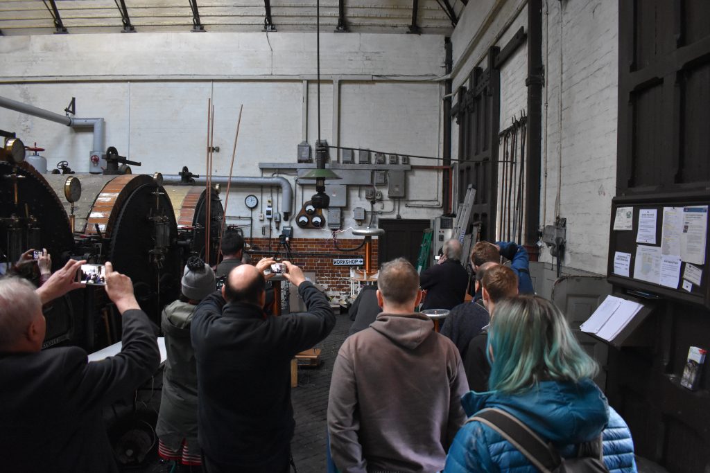
Another great High Voltage meet at Papplewick Pumping station this year.
These are some photos and videos from the event.
Derek’s Coils and Stuff…


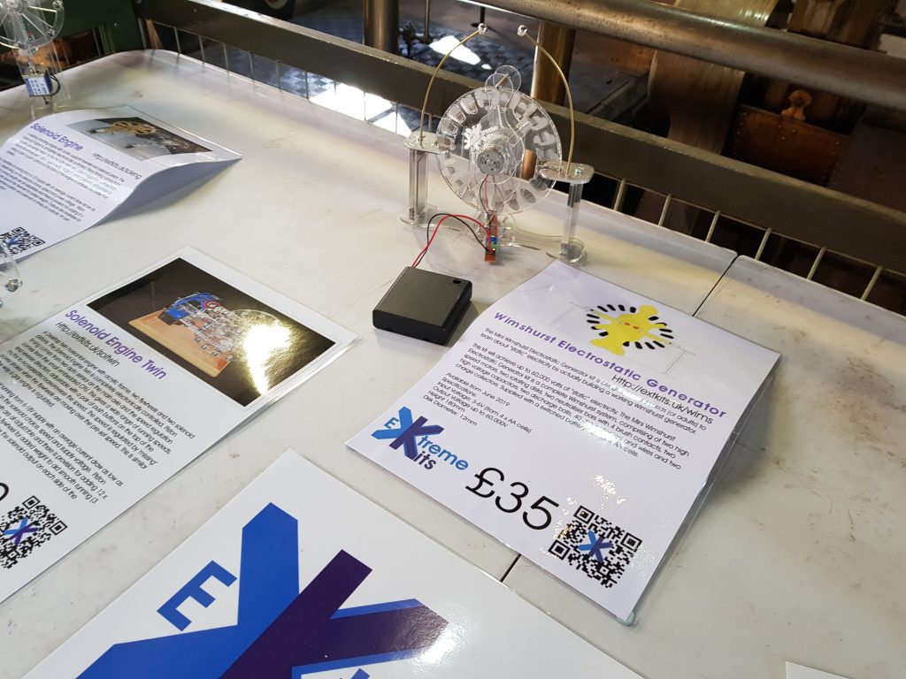
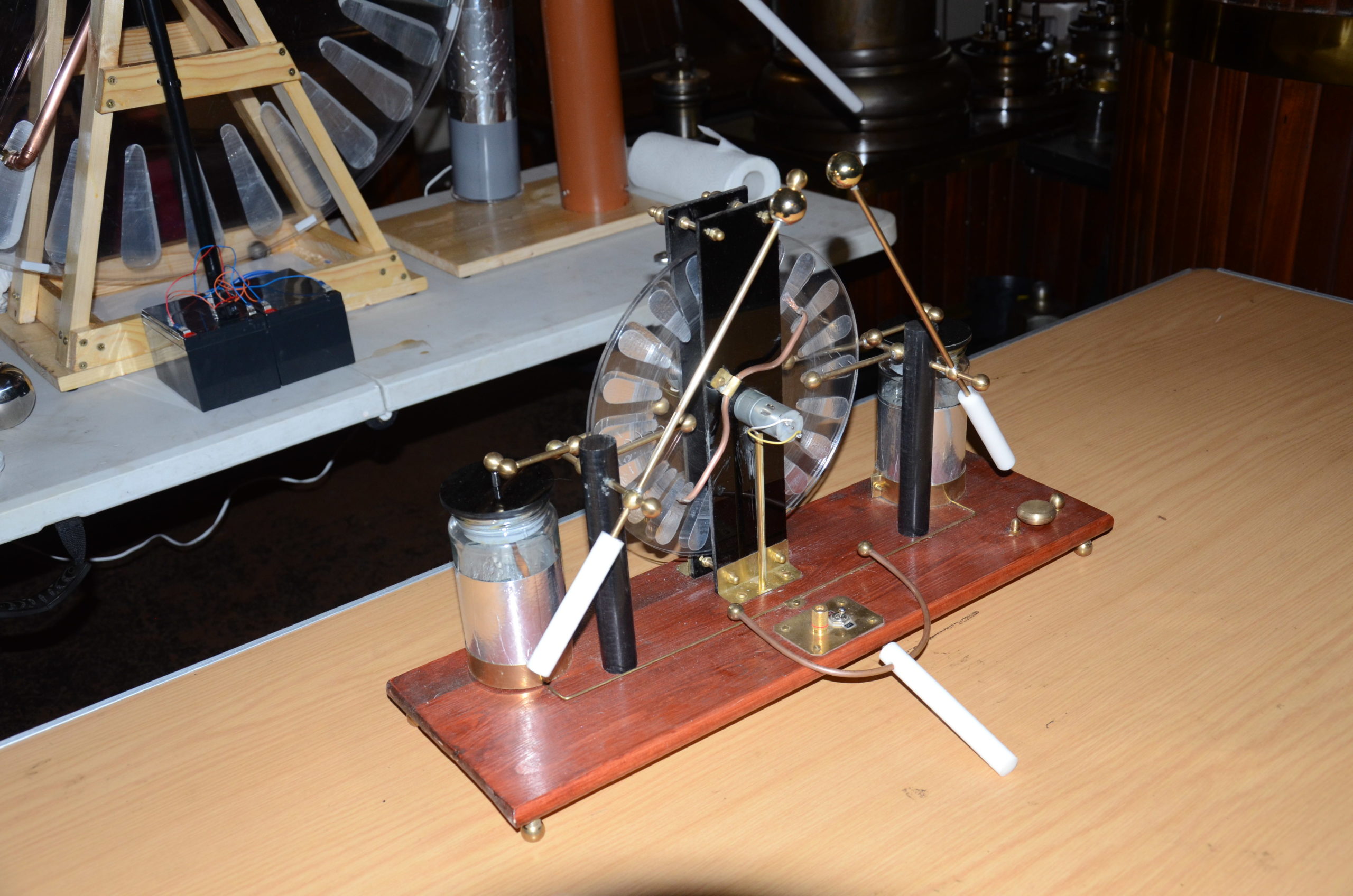
Extreme kits mini Wimshurst powers a ping pong accelerator
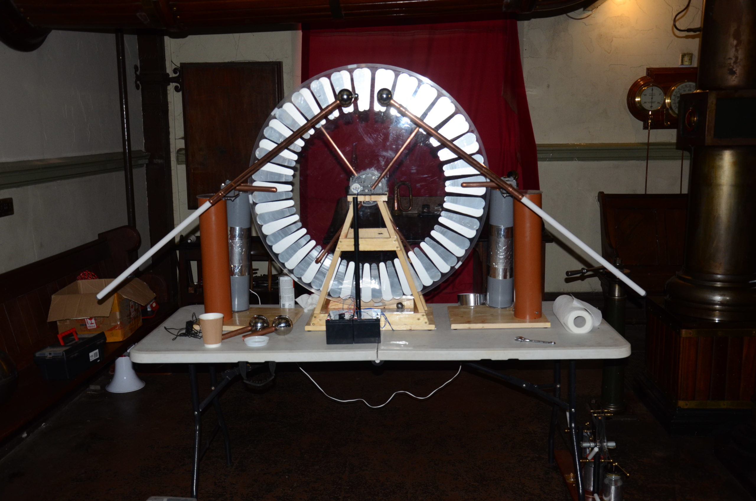
Large Wimshurst throws some sparks
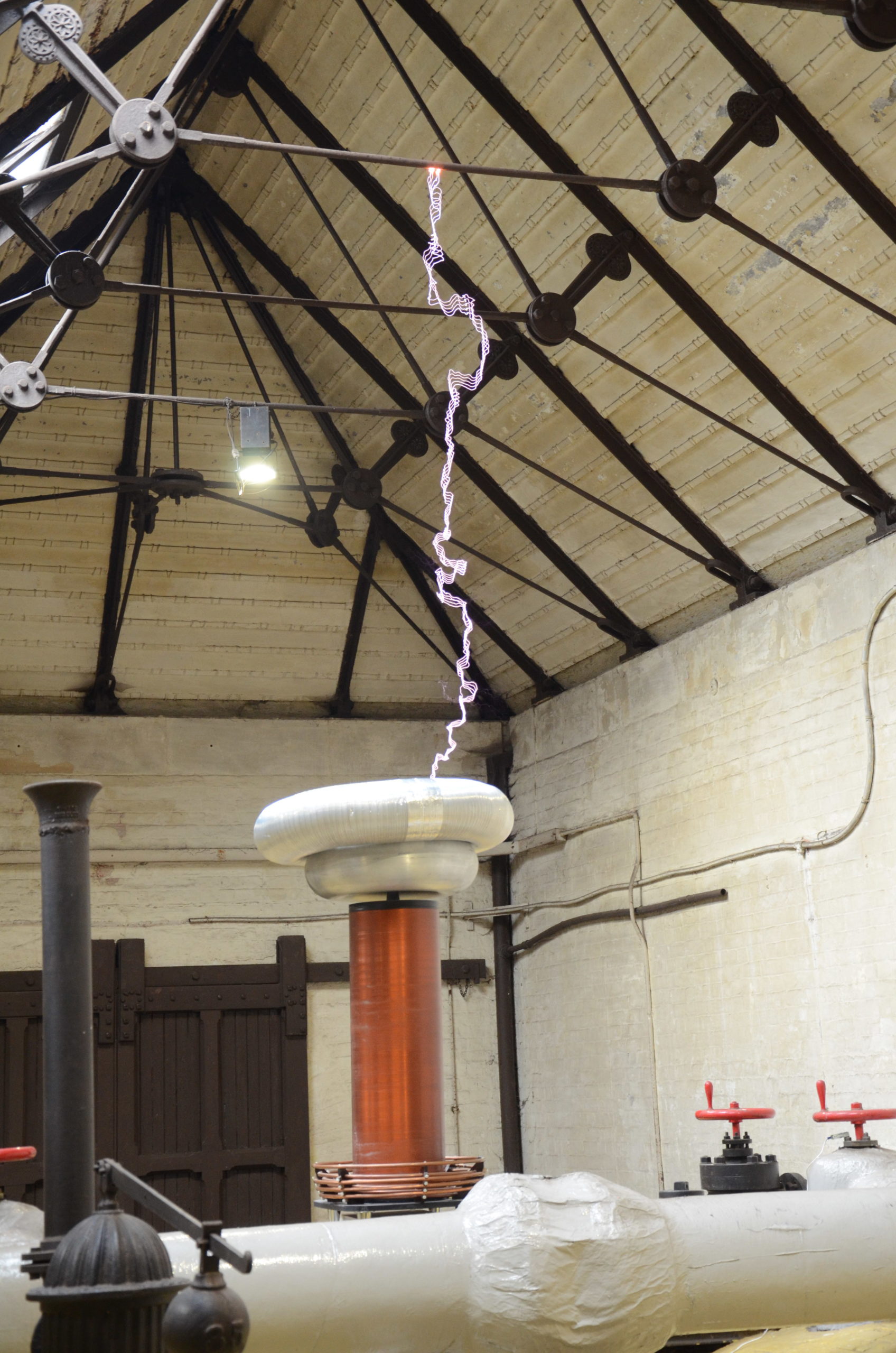
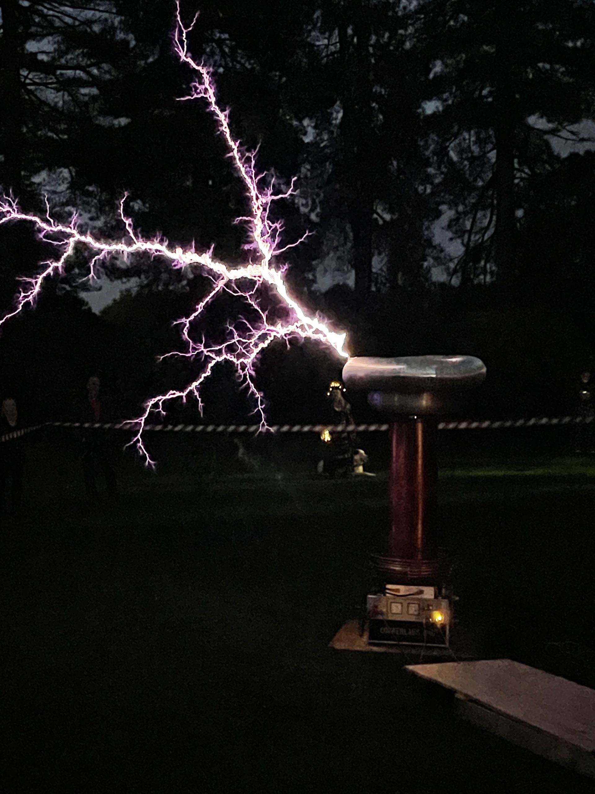
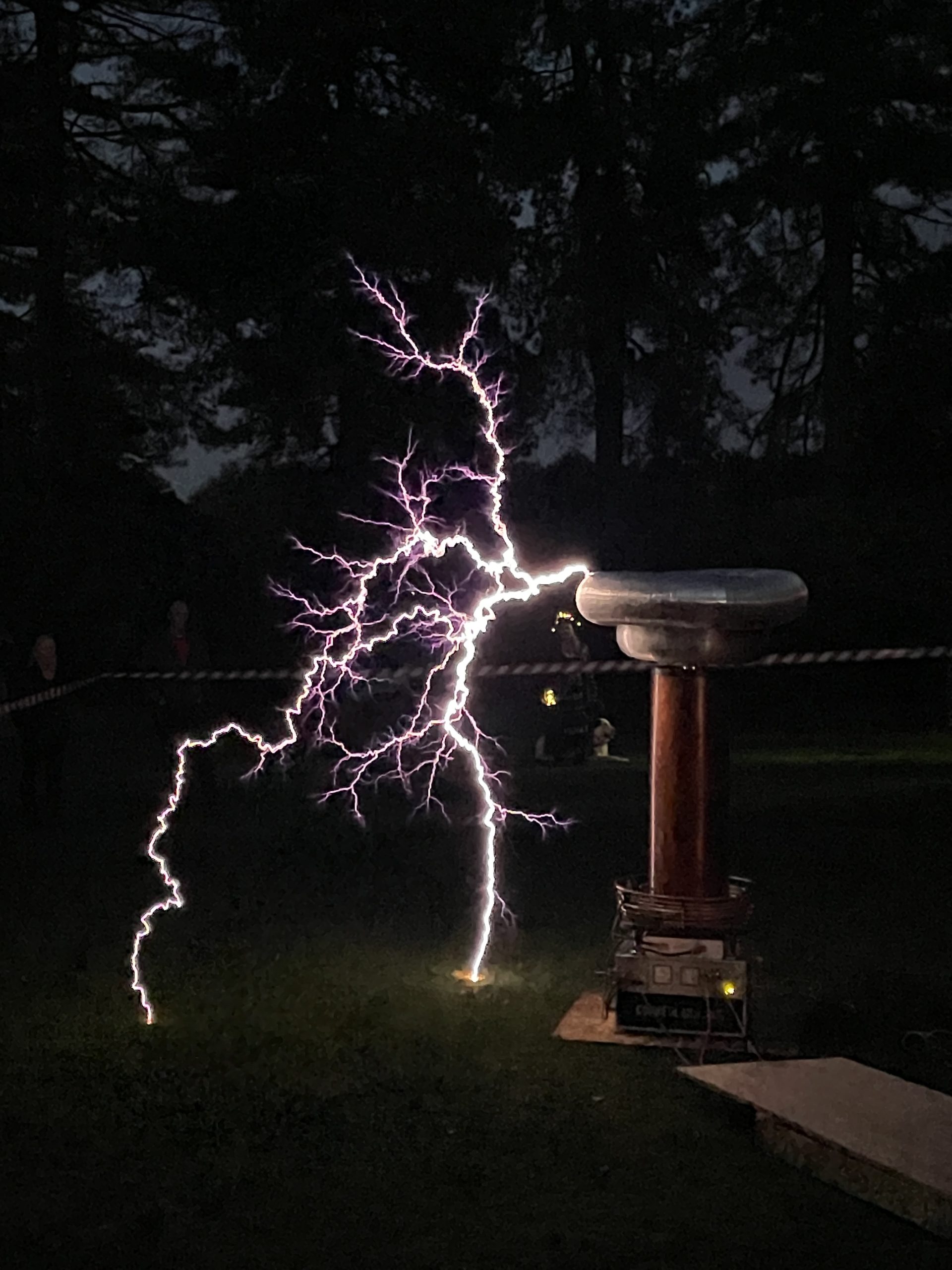
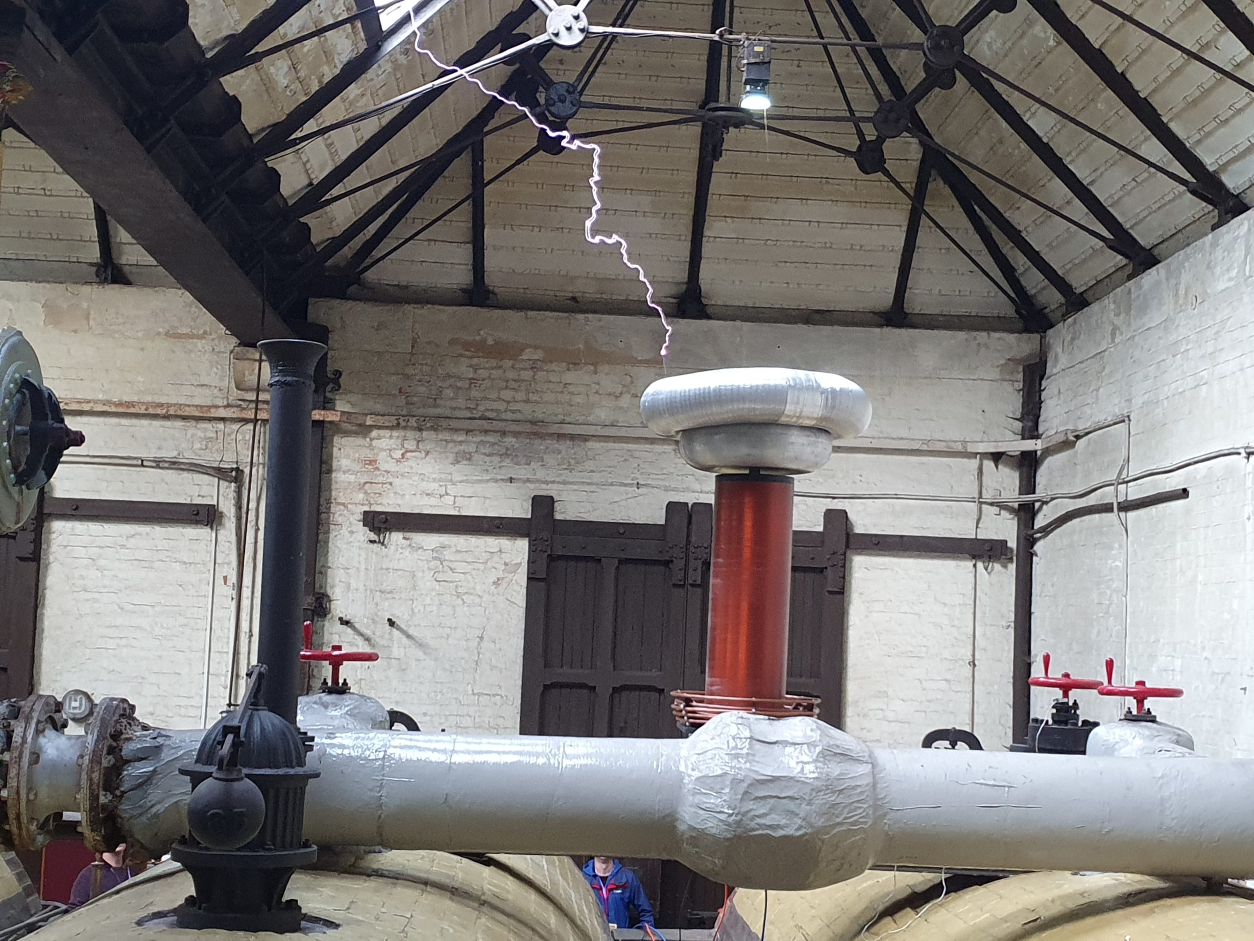
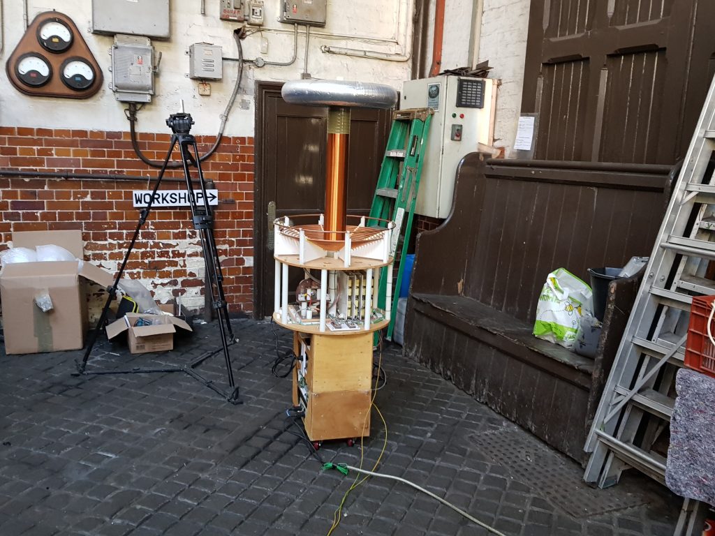
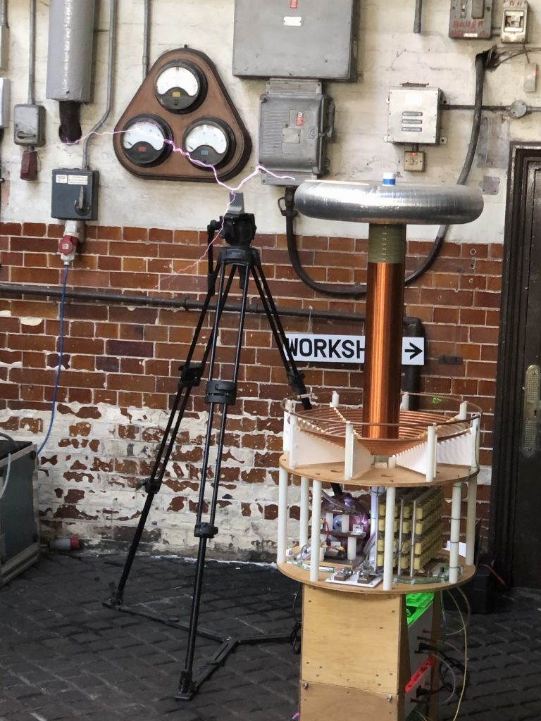
Steve’s Tesla Coil


Roger’s VDG, Geissler tubes and Wimshurst


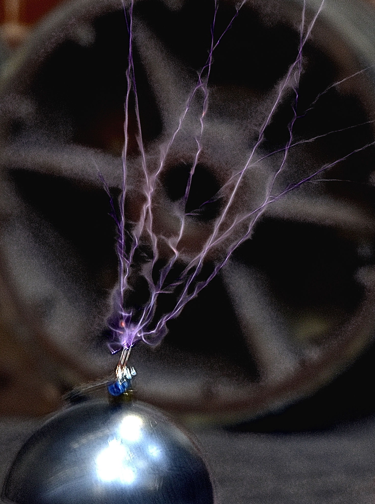
Van De Graaff with a charged ball
Alec’s Collection


Dave’s Coils


Andrew’s collection


Roberts stuff
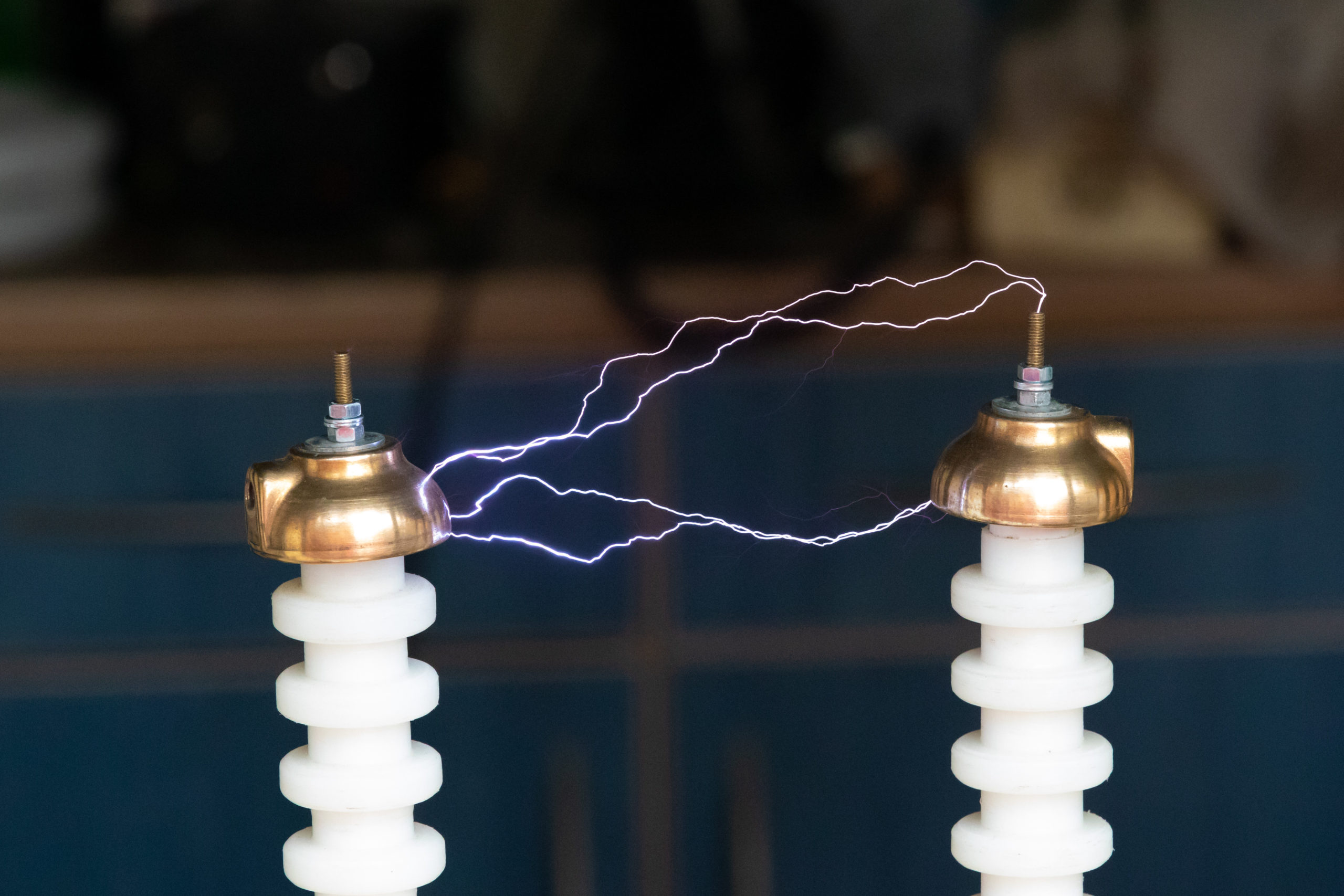
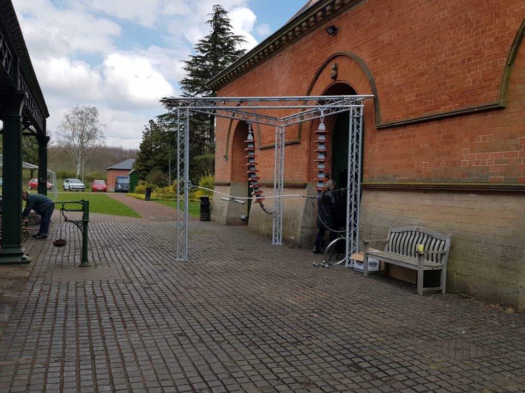
3 phase Jacobs ladder


Gary’s Jacobs ladder & Flyback TC


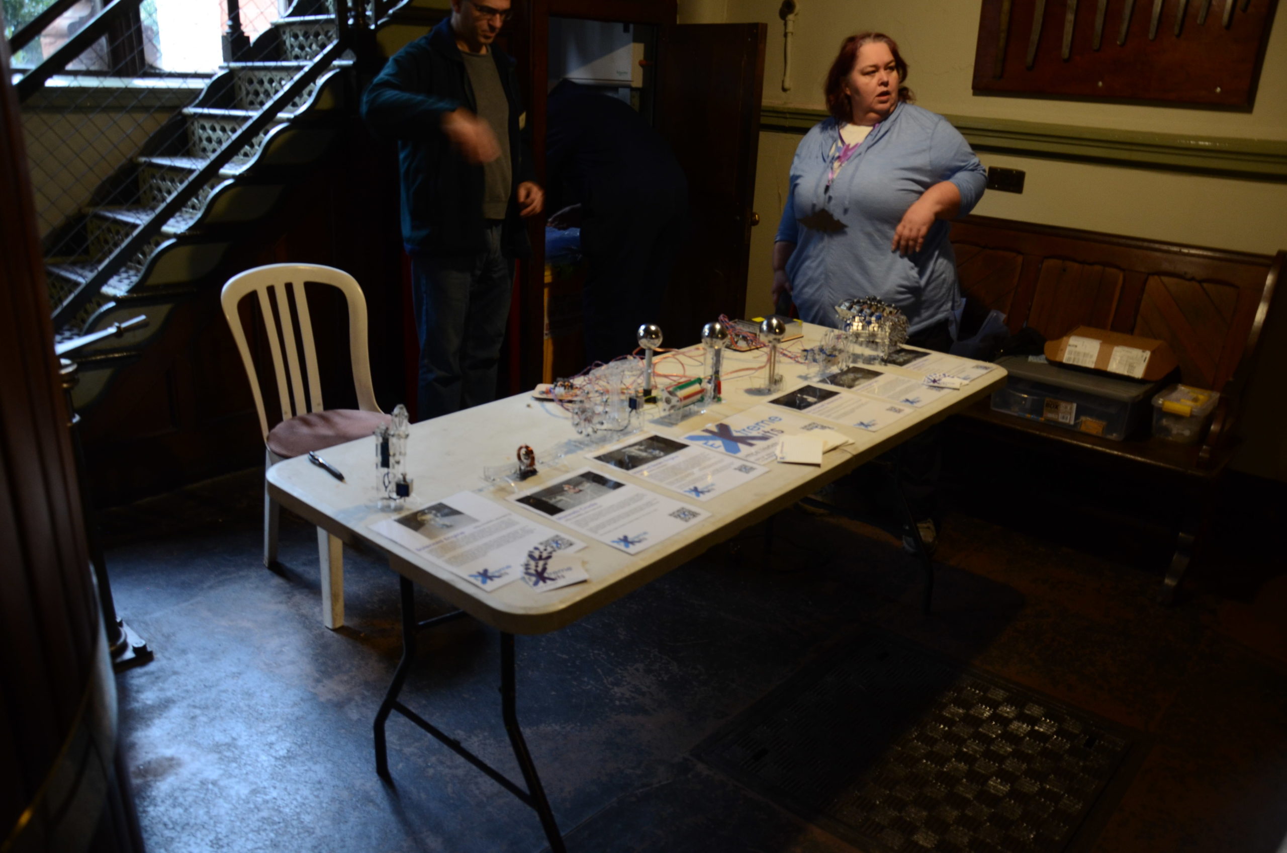
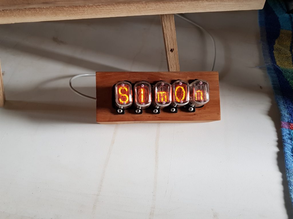
Simon and Mark


Carl’s Tesla coil

Thanks to Andy B and Alex L for many of the above and Mark K for these below.


Please return Its likely I’ll get sent more pics and videos that I’ll post here. (email me [email protected] if you have a pic or video)
I wanted to a cheap XY plotter to try some experiments and after looking at ebay I saw an inexpensive plotter to try, the Vigotec VG-A4
Construction was fairly easy, although the only instructions that came with the package were in Chinese. I have since found the instructions here Although due to translation issues, they are not much more help.
The Plotter was constructed and worked first time as a writer using the example JPG’s and the VigoTec Writer Software. (Downloadable here )

Be careful about belt tightness. If the belt it too tight you will easily loose position when moving. Otherwise the hardware is well made an designed.
I haven’t yet tried the Engraver software as this involved changing the firmware in the driver board.

All working well, I started to try driving the plotter by G-Code. There is of course Zero Documentation.
So after a lot of trying things I found the PenUP/Pen Down commands which are M03 and M05 respectively. You will need a delay for the pen server to do its thing, Im currently using G4 P1000 to give a 1 second delay.
This mostly works, as a test I put in a move G1 X Y Z and a pen down followed by a pen up. I did this 4 times to create a dot in each corner of a square, The pen only responded to two of them, I have no idea why.
The Writing software is very buggy. With many of the adjustments not working at all. I also find that you MUST do a pen down then a pen reset before using G-Code otherwise the pen wont work at all. (The pen UP button appears to do nothing. Unless you have loaded an image).
Be careful using G0 the plotter appears to lose position even with the lightest of pens. To cure this and especially if you are using anything heavier, use a G1 X Y Z FXXXX to set the feed rate. ( When using G-Code the speed slider is ignored)
There are some issues with G1 and pen up/down, but I haven’t fully discovered what the causes to these are or any solutions yet.
A friend of mine was asking me about MSF time reception and I realised I only knew some of the basics. So this sent me on a hunt for more information.
In the UK the MSF tme signal is sent on a carrier of 60khz from a transmitter in Anthorn Yorkshire with a radiated power if 17KW http://www.npl.co.uk/science-technology/time-frequency/products-and-services/time/msf-radio-time-signal
17KW sounds large, but this is at 60 Khz, the efficiency of ariels less than 2.5Km (a half a wavelength of 60Khz) long with all round coverage is going to be much less than 1, probably a lot less than 1. The old Time Signal transmitter at Rugby was in the order of 200KW. I can only assume the new transmitter is of a similar power to get a ERP of 17Kw.
After a little looking around, I discovered the web site of Andy (http://www.burningimage.net/msfsimulator) who has made a MSF transmitter for 60Khz using a Pc’s sound card using the third harmonic of 20Khz to produce a 60 Khz signal and written the Python code to encode a date time into the MSF protocol.
So with most of the heavy lifting done, I started to think about what I had to hand. Raspberry Pi’s…
My first thought was using the frequency generator built in to the PI to give the 60Khz as used in many PI transmitter projects , but there were limitations in trying to get 60Khz. So the next thought was a PWM output. A bit of googling gave me the formulae for the frequency of the hardware PWM on a PI
pwmClockDivisor=19200000/PWMRange/Freq
PWMrange is the number of “levels” you can specify for the PWM signal.
After some experimenting I found that you could set the range really small e.g. 2 Which is great if you sent the PWM a 0 it goes off. If you send it a 1 you get 50/50 Mark Space, ideal. Setting the pwmClockDivisor to 160 gives a 60Khz output.
The Wiring PI Wrapper for Python supports this setup. So setting the hardware PWM is a case of
io = wiringpi.GPIO(wiringpi.GPIO.WPI_MODE_PINS)
io.pinMode(PIN,io.PWM_OUTPUT)
io.pwmSetClock(160)
io.pwmSetRange(2)
The wiring Pi for Python setup is detailed here http://raspi.tv/how-to-install-wiringpi2-for-python-on-the-raspberry-pi
[code lang=”py”]
#——————————————————————-
# This script uses PWM on GPIO PIN 18 to transmit an MSF timecode
#
# Save it as msf.py somewhere on your Pi.
#
# Run it with ‘python msf.py’
#
# Requires the Wiring Pi Python Library
#
# Based on Audio MSF code from
#
# http://www.burningimage.net/msfsimulator
# by
# [email protected]
#
# PWM output, Frequency and DateTime Code Added by Derek Woodroffe
# [email protected]
#——————————————————————-
#——————————————————————-
# Set the time/date to transmit below.
#
# The date time startes at the datetime you set regardless of local
# clock settings
#
# Use groundhogday=True to repeat the same "day" every 24 hours.
#
# Your clock(s) should have set its time by around minute 5.
# Some clocks only look at MSF data every 12 hours.
#
# The day of the week is automatically set to the correct value
#——————————————————————-
import time
import math
import wiringpi
import datetime
#—————– Carrier Frequency ——————————
#UK tested, others un-tested not sure about the modulation
Freq=60000 #60Khz UK/Japan – 66.66Khz Russia – 77.5Khz Germany/Taiwan
#———————– Set inital time —————————
#start with a defined datetime
mmfdt = datetime.datetime(2019,4,1 ,6,1) #datetime year,month,day,hour,min
#Run with current time
#mmfdt = datetime.datetime.now()
#run 1 hour in the future
#mmfdt = datetime.datetime.now()+datetime.timedelta(0,0,0,0,0,1,0) #timedelta([days[, seconds[, microseconds[, milliseconds[, minutes[, hours[, weeks]]]]]])
#———————— Groundhogday —————————–
#repeat after 24 hours.
#groundhogday=True
#dont repeat
groundhogday=False
#———————— Parity ———————————–
# Set to 1 to transmit proper parity bits
enableparity = 1
#——————————————————————-
def carrier_on(length):
io.pwmWrite(PIN,1)
time.sleep(0.001*length)
def carrier_off(length):
io.pwmWrite(PIN,0)
time.sleep(0.001*length)
def minutemarker():
carrier_off(500)
carrier_on(500)
def send01():
carrier_off(100)
carrier_on(100)
carrier_off(100)
carrier_on(700)
def send11():
carrier_off(300)
carrier_on(700)
def send00():
carrier_off(100)
carrier_on(900)
def send10():
carrier_off(200)
carrier_on(800)
bcdlist= [80, 40, 20, 10, 8, 4, 2, 1]
#setup PWM GPIO pin 18 (pin1) Hardware PWM at Freq
PIN=1
#pwmClock divisor=19.2e6/2/Frequency
pwmClock=19200000/2/Freq
io = wiringpi.GPIO(wiringpi.GPIO.WPI_MODE_PINS)
io.pinMode(PIN,io.PWM_OUTPUT)
io.pwmSetClock(pwmClock)
io.pwmSetRange(2)
io.pwmWrite(PIN,0)
mmfdts=mmfdt
while(True):
year = mmfdt.year
month = mmfdt.month
dayofmonth = mmfdt.day
dayofweek = (mmfdt.weekday()+1) % 7 #0 = sunday, 1 = monday etc.
hour = mmfdt.hour
minute= mmfdt.minute
# Ignore the ‘0’ element in the list as it confuses matters
# with the timecode
timecodeA = [0] * 60
timecodeB = [0] * 60
# Convert the year to BCD and store in the correct place in the timecode
bcdindex=0
temp = year
sum=0
for i in range(17,25):
if temp >= bcdlist[bcdindex]:
timecodeA[i] = 1
sum += 1;
temp -= bcdlist[bcdindex]
bcdindex += 1
# Work out the parity bit for 17-24
if (sum % 2) != 1:
timecodeB[54] = enableparity
# Now do the month
bcdindex=3 #starts at 10
temp = month
sum = 0
for i in range(25,30):
if temp >= bcdlist[bcdindex]:
timecodeA[i] = 1
temp -= bcdlist[bcdindex]
sum += 1
bcdindex += 1
# Do the day of month
bcdindex=2 #starts at 20
temp = dayofmonth
for i in range(30,36):
if temp >= bcdlist[bcdindex]:
timecodeA[i] = 1
temp -= bcdlist[bcdindex]
sum += 1
bcdindex += 1
# Work out the parity bit for 25-35
if (sum % 2) != 1:
timecodeB[55] = enableparity
# Do the day of week
bcdindex=5 #starts at 4
temp = dayofweek
sum = 0
for i in range(36,39):
if temp >= bcdlist[bcdindex]:
timecodeA[i] = 1
temp -= bcdlist[bcdindex]
sum += 1
bcdindex += 1
# Work out the parity bit for 36-38
if (sum % 2) != 1:
timecodeB[56] = enableparity
# Do the hour
bcdindex=2 #starts at 20
temp = hour
sum = 0
for i in range(39,45):
if temp >= bcdlist[bcdindex]:
timecodeA[i] = 1
temp -= bcdlist[bcdindex]
sum += 1
bcdindex += 1
# Do the minute
bcdindex=1 #starts at 40
temp = minute
for i in range(45,52):
if temp >= bcdlist[bcdindex]:
timecodeA[i] = 1
temp -= bcdlist[bcdindex]
sum += 1
bcdindex += 1
# Work out the parity bit for 36-38
if (sum % 2) != 1:
timecodeB[57] = enableparity
#Bits 53A – 58A should always be 1
for i in range(53,59):
timecodeA[i] = 1
print(str(year).zfill(2) + "-" + str(month).zfill(2) + "-" + str(dayofmonth).zfill(2) + " " + str(hour).zfill(2) + ":" + str(minute).zfill(2)+ " – " + str(dayofweek) )
#print("A bits: " + str(timecodeA[1:]))
#print("B bits: " + str(timecodeB[1:]))
# Now play the timecode out
minutemarker()
for i in range(1,60):
if (timecodeA[i] == 1) and (timecodeB[i] == 1):
send11()
elif (timecodeA[i] == 0) and (timecodeB[i] == 1):
send01()
elif (timecodeA[i] == 0) and (timecodeB[i] == 0):
send00()
elif (timecodeA[i] == 1) and (timecodeB[i] == 0):
send10()
mmfdt = mmfdt + datetime.timedelta(0,60) #timedelta([days[, seconds[, microseconds[, milliseconds[, minutes[, hours[, weeks]]]]]]])
if (groundhogday):
if (mmfdt-mmfdts>datetime.timedelta(1)):
#restart day
mmfdt=mmfdts
print ("RESTART DAY")
[/code]
Then
io.pwmWrite(PIN,1) turns on the 60 Khz and io.pwmWrite(PIN,0) turns it off.
I replaced all of Andy’s Sound Card Code with functions that mimicked the operation, but used the PWM commands above and a sleep to give me the correct on/off times (yes, sleep is inaccurate, this could be improved)
Adding a short wire to GPIO 1 (PIN18) and placing this near an MSF clock, worked… (it was 4 in the afternoon, and not April 1st 2019)

But if you want some fun, this close is probably not enough 🙂
Note: Transmitting on this frequency is Illegal and It is possible to affect all sorts of equipment that uses MSF. The transmitter below has a range of only a few feet and so is unlikely to cause any unexpected effects, but don’t do this where there is any medical or industrial control equipment that may use the time signal.
Oh, and your neighbour may get quite miffed if his alarm clock goes off at the wrong time…
So adding some power..

I made an X of 300mm strips of MDF and wound 100Turns of 0.3mm enamelled wire around the structure.
This I drove from a MC4428 mosfet driver. Using both channels together gives a full bridge drive of up to 1.5A and can run up to 24V.

C1 will need to be modified to get your coil in tune. Tuning can easily be done by monitoring the Cap to coil connection and varying the value of C1 for maximum voltage. Beware that the voltage on C1 can get to about 100V when in tune, so keep it away from your PI#s GPIO
(And other things too)
The Circuit generates about 1W of power, but remember the ariel is only a fraction of the 2.5Km dipole required for 1:1 ERP , so the actual ERP is much lower. Mine will “correct” clocks time at a range of about 4-5 Meters.


